Application
- Power supply and control of external switch systems in high-voltage substations (110 kV, 220 kV and 400 kV), secondary circuits, automation systems;
- station circuit protection;
- Measurement of station parameters and data transmission.
Equipment
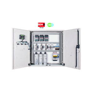
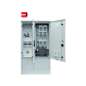
Housing
Aluminum OU-1SKS/OU-2SKS
- single shell – outer shell;
- single shell with thermal insulation – outer shell with thermal insulation mat Al;
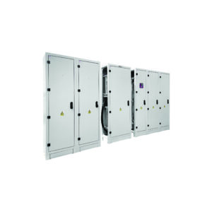
- Double-shell with air gap – outer shell and inner shell with air space;
- double-shell with insulation – the space between the shells filled with non-flammable rock wool;
- Outdoor, free-standing on a concrete or metal foundation;
- Made of aluminum sheet joined by welding and riveting;
- The thickness of the sheet metal adapted to the dimensions;
- Powder coating in any color (RAL) and surface texture with high resistance to deterioration and external factors;
- Connected to the foundation with screws;
- made in protection class I or II;
- Degree of protection up to IP 44 – 55;
- Mechanical resistance: up to IK10.
Equipment is selected each time according to the needs of the customer.
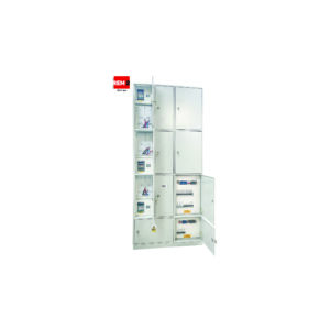
Mounting elements
- Vertical mounting profiles – permanently attached to the walls of the enclosure suitable for mounting plates or current path support insulators;
- Mounting plate – galvanized, mounted on vertical mounting profiles made of galvanized sheet metal under the current track insulators;
- Comb trays – with a cross-section adapted to the type and amount of cabling;
- Masking plates – made of plastic plates or metal sheets, mounted to the housing structure or internal frame, with the help of mask plate brackets;
- Control panel with synoptic board – made in a unique way, by applying offset printed adhesive sheets to the entire surface of the board, with the possibility of printing any graphics. Mounted in an internal frame;
- Lighting and heating – heating circuits – a thermostat along with a heater located in the lower part of the cabinet. Lighting – two fluorescent lamps, assembled in the upper part, thanks to which we get an even intensity of lighting across the width. Limit switches and a panel switch are mounted in the cabinet (it is possible to mount the apparatus anywhere according to the customer’s requirements);
- Cable holders with mounting bar;
- Galvanized steel grounding rail;
- Ventilation – allowing constant airflow through the use of a fan and proper opening of the housing;
- Document pocket.
The enclosure can additionally contain the circuits of the basic electrical system prepared by the designer in each case, depending on the specific project.
Doors
- full;
- single-sided or double-sided, for better access to the apparatus;
- Single-leaf or double-leaf;
- Locked with a cylinder lock (any shape) or a basquil lock locked with a system cylinder and an additional padlock;
- three-point locking;
- Interior hinges with an anti-intrusion catch;
- opening angle 120 deg;
- Grounding studs with wiring.
Roof
- Gabled roof with a ventilation maze and ventilation to prevent the accumulation of water and moisture.
Basis
- has an opening that allows cables from the cable duct to enter through an additional fire bulkhead;
- Prepared for the fire bulkhead, using bolted connections.
Dimensions
Dimensions adapted to the type, amount of equipment and individual needs of the customer. Typical implementations:
- height: 1100/1900/2100/2200 mm;
- width: 400/600/800/820/850/1000/1050/1250/1400 mm;
- depth: 250/300/400/600/620/800 mm.
Apparatus
In the cabinet are placed circuits of the basic and additional electrical installation each time prepared by the designer, depending on the specific investment.
Apparatus and strip connectors are arranged on mounting plates, TH35 rails between comb trays in any configuration (vertical or horizontal).In the cabinet are placed circuits of the basic and additional electrical installation each time prepared by the designer, depending on the specific investment.Apparatus and strip connectors are arranged on mounting plates, TH35 rails between comb trays in any configuration (vertical or horizontal).
- lighting and heating of the cabinet – Heating circuits – a thermostat along with a heater located in the lower part of the cabinet. Lighting – two fluorescent lamps, assembled in the upper part, thanks to which we get an even intensity of lighting across the width. Limit switches and a panel switch are mounted in the cabinet (it is possible to mount the apparatus anywhere according to the customer’s requirements).
- technical outlet circuit – supplied from a separate circuit from the switchboard of own needs. The 1-phase and 3-phase sockets are located outside the cabinet under a cover.
- secondary circuits – Apparatus and configuration of voltage circuits are selected according to project documentation and customer requirements.
- motor drive circuit- fuses and circuit breakers and strip connectors are selected according to project documentation and customer requirements.
Wiring
- Wiring of cabinets is made by insulated wire with cross sections of 1.5 to 16 mm2, depending on the type of circuit and apparatus.
Signs
- External marking of cabinets is made by laser engraving technique, on metal or plastic plates of any color. Marking of apparatus and wiring is carried out on the basis of the PN-EN 61082-1 standard. Apparatus and letter connectors marked according to the internal wiring diagram and according to design guidelines. Synoptic boards made in a unique way, by applying printed off-set adhesive sheets to the entire surface of the mounting plate, with the possibility of printing any graphics.
Accessories
- FB concrete or FM aluminum foundation – matched to the dimensions of the cabinet;
- “GO” fire bulkhead – prevents fire and other agents from entering the cabinet.
Rated parameters
| Rated switching voltage: | 230/400 V |
| Napięcie znamionowe izolacji: | 500 V |
| Rated frequency: | 50 Hz AC, DC |
| IP rating: | 44 – 55 |
| IK degree of mechanical resistance: | 10 |
| Protection class: | I/II |
| Height/Width/Depth: | unbound |
Compliance with standards
PN-EN 61439-1
“Low-voltage switchgear and controlgear – Part 1: General provisions”;
PN-EN 61439-2
“Low-voltage switchgear and controlgear – Part 2: Switchgear and controlgear
for power distribution”;
PN-E-05163
„Shielded low-voltage switchgear and controlgear. Guidelines for testing under conditions of arc discharge, resulting from an internal short circuit”;
PN-EN 50274
„Low-voltage switchgear and controlgear – Protection against electric shock – Protection against unintentional direct contact of hazardous live parts”;
PN-EN 62208
„Empty enclosures for low-voltage switchgear and controlgear. General requirements”;
PN-EN 60529
„Degrees of protection provided by enclosures (IP Code)”;
PN-EN ISO 4628
„Paints and varnishes – Evaluation of damage to coatings – Determination of the amount and extent of damage and the intensity of uniform changes in appearance – Part 6: Evaluation of the degree of chalking by the tape method”;
PN-EN ISO 2409
„Paints and varnishes – Testing by the notch grid method”;
PN-EN 62262
„Degrees of protection against external mechanical impacts provided by enclosures of electrical equipment (IK code) (IDT PN-EN 50102:2001)”.