Application
- For industrial, non-industrial, energy, utility and commercial facilities, container stations and others;
- As main switchgear, branch switchgear or shunting-station switchgear;
- Protection of electrical equipment against the effects of short circuits and overloads on the LV side;
- Distribution and measurement of electricity.
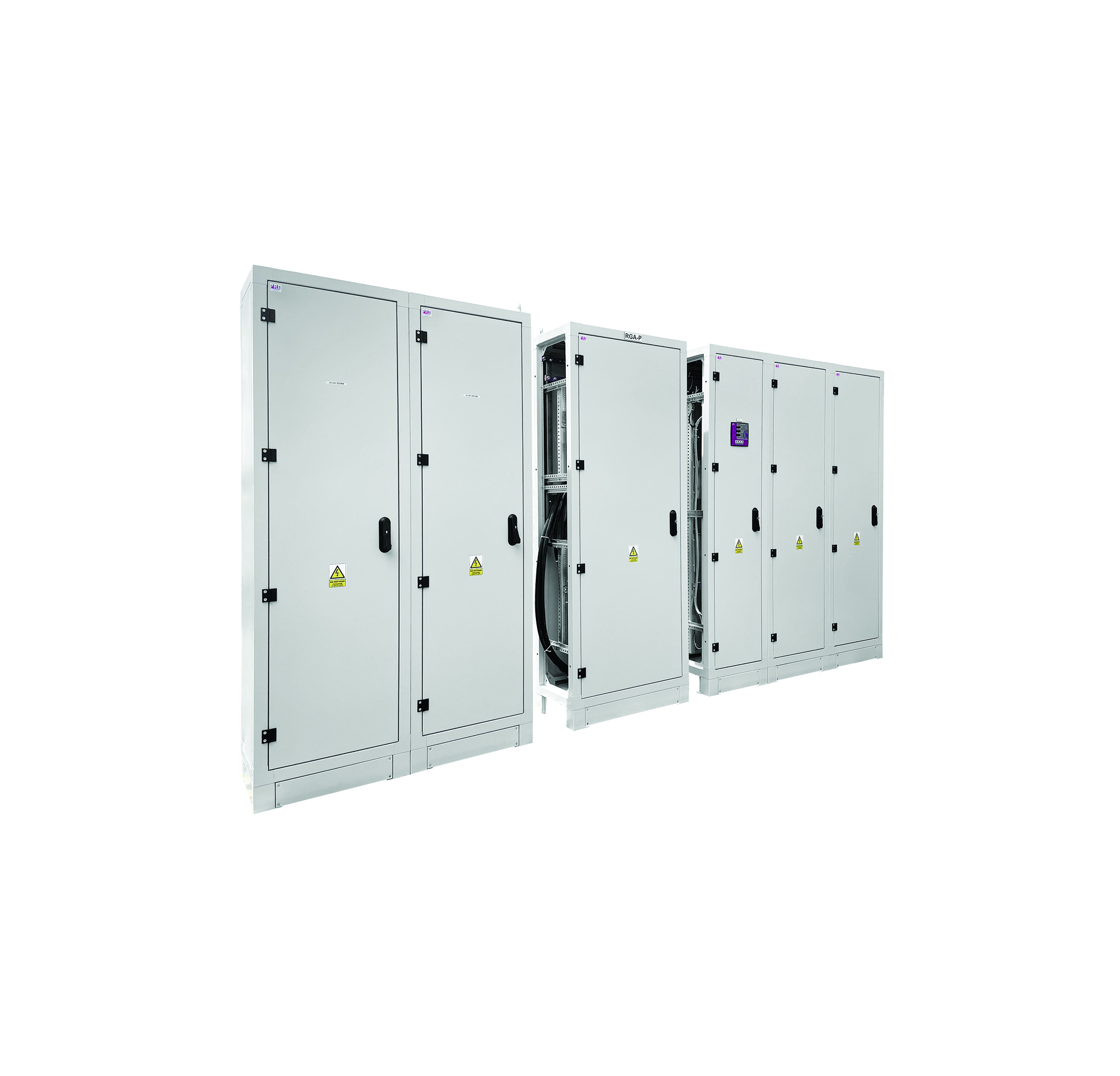
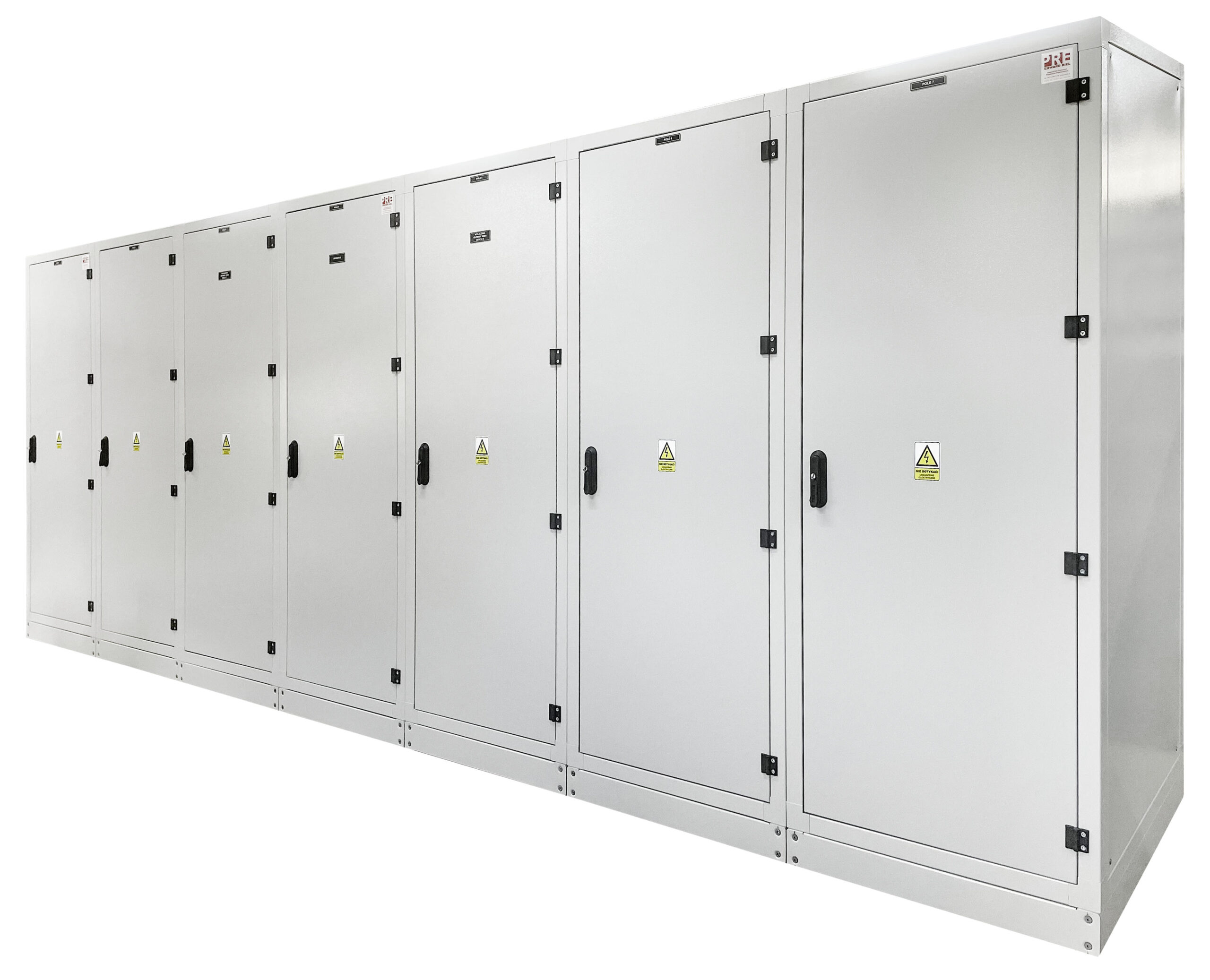
General characteristics
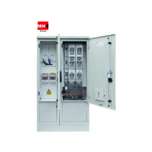
RP industrial switchgear is characterized by simple and clear electrical connection layouts and has a design that guarantees safe operation. Thanks to the high degree of IP protection (IP 4X – IP 54), RP switchgears can be used directly next to machinery and equipment. A very important aspect in the construction of our switchboards is their reliability and easy expandability.
The main advantages:
- resistance to mechanical damage;
- clear layout of connections;
- safety of operation;
- operational reliability;
- easy expandability.
Equipment
Configurations
A.MZ – power module – equipped with a disconnector (max. 4000 A) or power switch (max. 4000 A), having the ability to block opening under load, cable entry from above or below by means of rail or cable connections;
B.MS – Coupling module – operation in SZR systems together with power supply modules, cable entry from above or below by means of rail or cable connections;
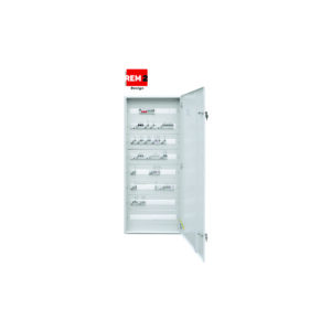
B.MP – outflow module – Equipped with strip fuse disconnectors, box fuse disconnectors or power circuit breakers (from 160A to 1250A), available apparatuses: NSL, SL, ARS, LTL, SLBM, RBK, RB-2(s), others, insert size gr. 00 – 4
- Power supply made as cable, V-type terminals for two cables up to 240mm2;
- Current tracks with a cross-section adapted to the load (Cu), PEN bus with the possibility of splitting into PE and N;
- Shielded reserve circuits;
D.BK – reactive power compensation module – Inductive and capacitive reactive power compensation up to 400 kVar.
E. other modules – Such as control or communications.
RP industrial switchgear has distribution, protection and control apparatus for main and auxiliary circuits, which can be installed as members:
- Fixed, where all parts of the apparatus are permanently mounted on a plate or TH35 rail;
- slide-out, either as a single camera or a set of cameras that are mounted in a slide-out tray.
RP industrial switchgear is also made on the basis of other manufacturers’ systems.
Enclosure
Steel OU-1/OU-2 or Aluminum OU-1S
- Indoor or outdoor, free-standing or wall-mounted on a pedestal;
- Skeletal, made of a steel frame sheathed in steel or aluminum sheets (joining by welding and bolted connections);
- Powder coating in any color (RAL) and texture
- Pavement with high resistance to deterioration;
- Combined with a plinth;
- Polyurethane foam seals;
- Made in protection class I or II;
- Degree of protection up to IP 55;
- Mechanical resistance: up to IK 08.
Mounting components
- Vertical mounting profiles – steel, hole-punched, mounted to the frame;
- Mounting plate – galvanized, mounted on vertical mounting profiles made of galvanized sheet metal under the current track insulators;
- Comb trays – with a cross-section adapted to the type and amount of cabling;
- Internal frame tilting 19” – symmetrical or asymmetrical;
- Cable holders with mounting bar;
- Masking plates – made of plastic plates or metal sheets, mounted to the housing structure or internal frame, with the help of mask plate brackets;
- Control panel with synoptic board – made in a unique way, by applying offset printed adhesive sheets to the entire surface of the board, with the possibility of printing any graphics. Mounted in an internal frame;
- Lighting – two fluorescent lamps, assembled in the upper part, thanks to which we get an even intensity of lighting across the width. In the cabinet are mounted limit switches and a panel switch (it is possible to mount the apparatus anywhere, according to customer requirements);
- Ventilation – allowing constant airflow through the use of a fan and proper opening of the housing.
Frame – steel frame
- Made of steel profiles joined by welding;
- A hole for attaching a mounting plate or vertical mounting profiles;
Side covers
- Mounted to the frame with allen key screw connections;
- The thickness of the sheet metal adapted to the dimensions;
- When the side covers are installed, the width dimension of the housing does not change.
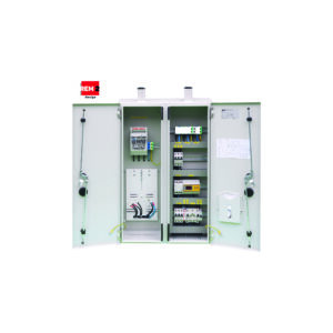
Doors
- solid or transparent;
- single-sided or double-sided (back cover), for better access to the apparatus;
- Single-leaf or double-leaf;
- Locked with a cylinder lock (any shape) or a basquil lock locked with a system cylinder and an additional padlock;
- three-point locking;
- internal hinges;
- opening angle 120 deg;
- Grounding studs including wiring.
Roof
- Made of a height-adjustable cover for additional ventilation;
- The cover has an additional hole, with grommets, to allow the introduction of wiring from cable routes;
- Transport handles.
Basis
- An opening with a cable grommet to allow cables to enter from the cable duct;
- Prepared for mounting the pedestal with screw connections.
Dimensions
Dimensions adapted to the type, amount of equipment and individual needs of the customer.
Typical implementations:
- height: 1800/2000/2200 mm;
- width: 400/600/800/850/1000/1050/1250/1400 mm;
- depth: 250/300/400/600/800 mm
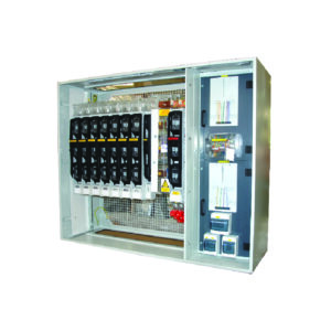
Modular housing
- A small-sized, lightweight modular skeletal structure made of galvanized steel or aluminum profiles connected by cast connectors made of aluminum or polyamide, allowing tool-free connection of individual elements and ensuring adequate rigidity of the structure;
- High mechanical strength and a degree of protection that prevents the ingress of dust and mechanical damage;
- Fully shielded, covers made of steel sheet coated with anti-corrosion, powder coated in any color, made in a fixed or tilting version that allows inspection and examination with a thermal imaging camera;
- Internal space with separated parts: functional modules, current paths;
- Allows you to change the power supply side independently, either by repositioning the switchgear power module or swapping it with the metering module;
- Connection of individual modules made by screw connections (without riveting or welding) allows quick disassembly of modules, bringing the switchboard in modules to the place of foundation in the room (lack of space) and their reassembly;
- Set on an additional frame, matching the dimensions of the cable channel;
- The dimensions of the switchboard are arbitrary, adapted to the individual needs of the customer;
- Connecting a clique of modules at a 90-degree angle;
- handles to allow transport by crane or overhead crane.
Accessories
- plinth – made in solid or ventilated version with any height.
Signs
External marking of cabinets is made by laser engraving on metal or plastic plates of any color, marking of apparatus and wiring is carried out on the basis of PN-EN 61082-1 standard.
Electrical apparatuses are described according to the internal wiring diagram and according to design guidelines. Synoptic boards made in a unique way, by applying offset printed sheets to the entire surface of the mounting plate, with the possibility of printing any graphics.
Stapling made with Cu rails depending on the required current carrying capacity and type of apparatus. Cu-rails can be located in any part of the module (top, back, bottom) thanks to the profiling, they provide easy access when connecting wiring.
Rated parameters
| Rated switching voltage: | 230 V / 400 V |
| Rated insulation voltage: | 500 V / 690 V |
| Rated frequency: | 50 Hz |
| Surge voltage withstanding: | 8 kV |
| Rated continuous current of the main rails: | 1250/1600/2500/4000 A |
| Rated continuous current of drain rails: | 160/250/400/630 A |
| Rated short-term withstand current: | 40 kA (1 s.) |
| Rated peak withstand current: | 80 kA |
| Short-circuit current of internal arc discharge: | 20 kA |
| IP rating: | 4X/2X, 44-55 |
| IK degree of mechanical resistance: | 10 |
| Protection class: | I |
| Dimensions of the supply/receiving terminals: | unbound |
| Network layouts: | TN-S, TN-C, TN-C-S, TT, IT |
| Height/Width/Depth: | unbound |
Compliance with standards
PN-EN 61439-1
“Low-voltage switchgear and controlgear – Part 1: General provisions”;
PN-EN 61439-2
“Low-voltage switchgear and controlgear – Part 2: Switchgear and controlgear for power distribution”;
PN-E-05163
“Shielded low-voltage switchgear and controlgear. Guidelines for testing under arc discharge conditions resulting from an internal short circuit”;
PN-EN 50274
“Low-voltage switchgear and controlgear – Protection against electric shock – Protection against unintentional direct contact of hazardous live parts”;
PN-EN 60529
” Degrees of protection provided by enclosures (IP Code)”;
PN-EN 62208
“Empty enclosures for low-voltage switchgear and controlgear. General requirements”;
PN-EN 62262
“Degrees of protection against external mechanical impact provided by enclosures of electrical equipment (IK code) (IDT PN-EN 50102:2001)”;
PN-EN ISO 4628
“Paints and varnishes – Evaluation of deterioration of coatings – Determination of the amount and extent of damage and the intensity of uniform changes in appearance – Part 6: Evaluation of the degree of chalking by the tape method”.
PN-EN ISO 2409
“Paints and varnishes – Testing by the notch grid method”.