Application
- basic equipment of high-voltage substations (100 kV, 220 kV and 400 kV);
- Control of circuits and apparatus: relay, protection, communication, own needs, measurement;
- Protection of secondary circuits of the station (disconnectors, switches);
- Measurement of station parameters and data transmission;
- Protection of electrical equipment against the effects of short circuits and overloads.
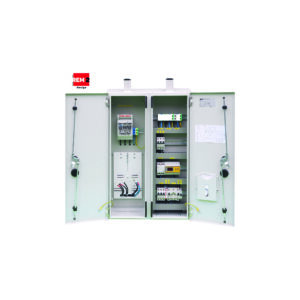
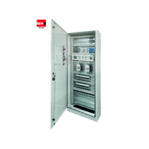
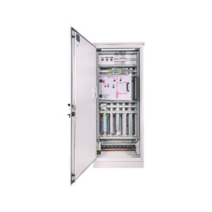
Types of enclosures
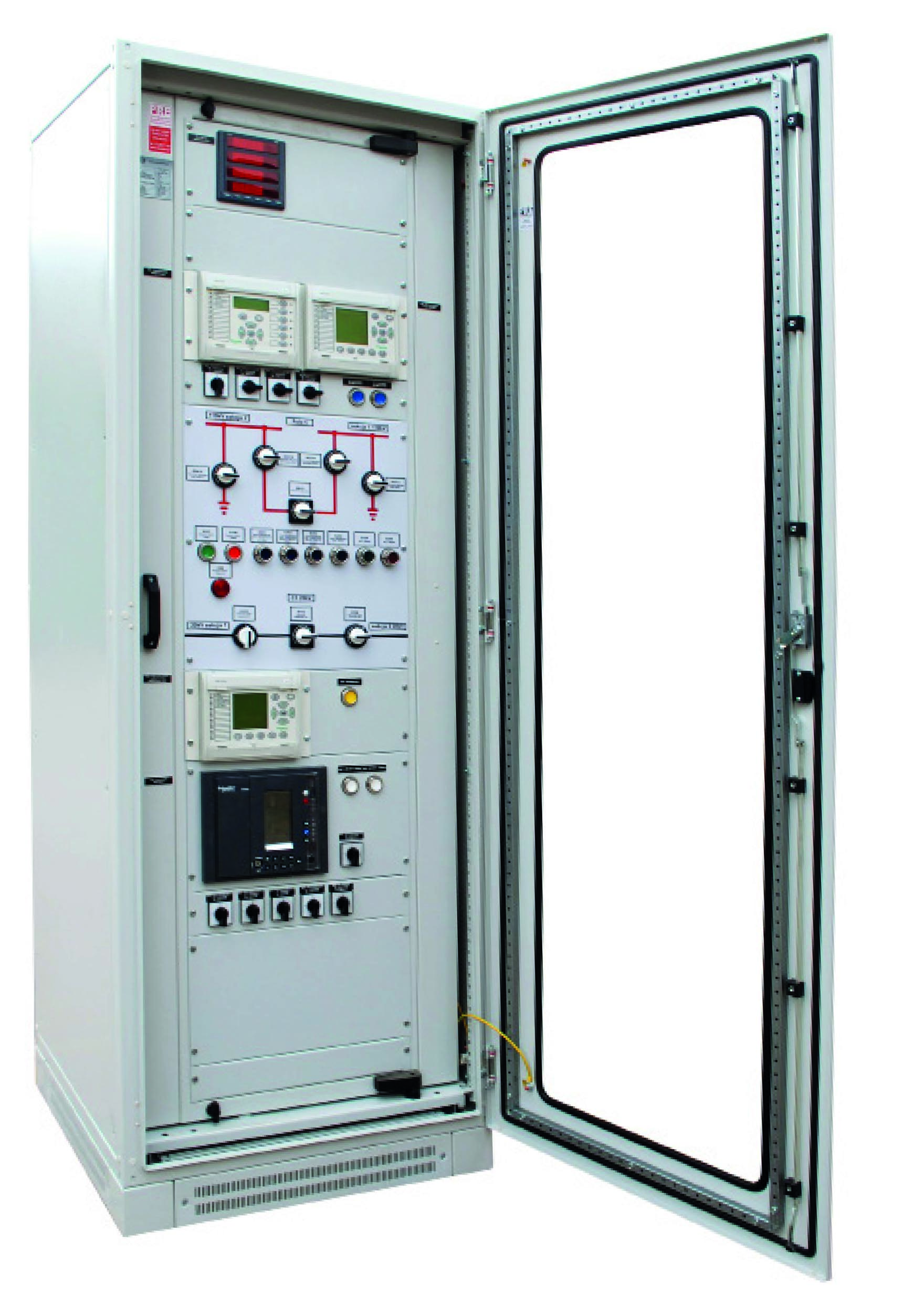
- Protection – protection of 110 kV, 220 kV, 400 kV lines, transformers and couplers, equipped with earth fault protection, differential protection, overcurrent protection, autonomous protection, field controllers, analyzers and other equipment depending on the station configuration;
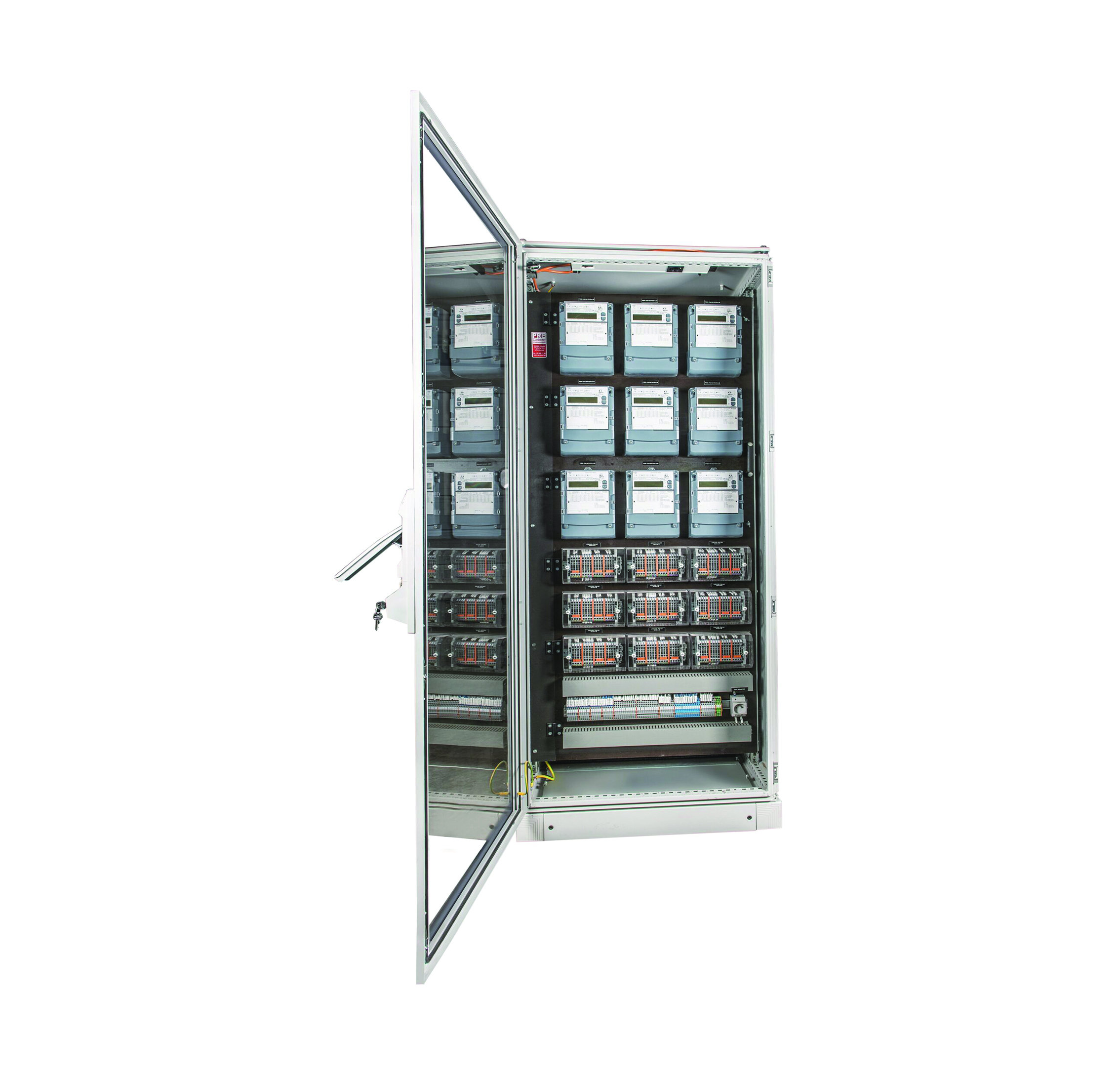
- Measuring– measurement of energy consumption of individual circuits of the station.Equipped with meter mounting plate in fixed or tilting version, energy meters, measuring strips and other necessary apparatus and strip connectors;
- Own needs 400/230 VAC – power supply of the station’s own switchgear circuits, equipped with the automatic АВР system, contactors, power circuit breakers, overcurrent circuit breakers, current and voltage measurement apparatus, central signaling, other remaining apparatus led out to strip connectors;
- Own needs 110/220 VDC – DC circuit power supply, equipped with a rectifier with current measurement and an external battery pack;
- Guaranteed voltages 230 VAC, 24-48 VDC – power supply of secondary circuits of emergency signaling and control protection, equipped with inverters and power supplies, disconnectors, overcurrent circuit breakers, current and voltage measurement apparatus, central signaling, other other apparatus brought out on strip connectors;
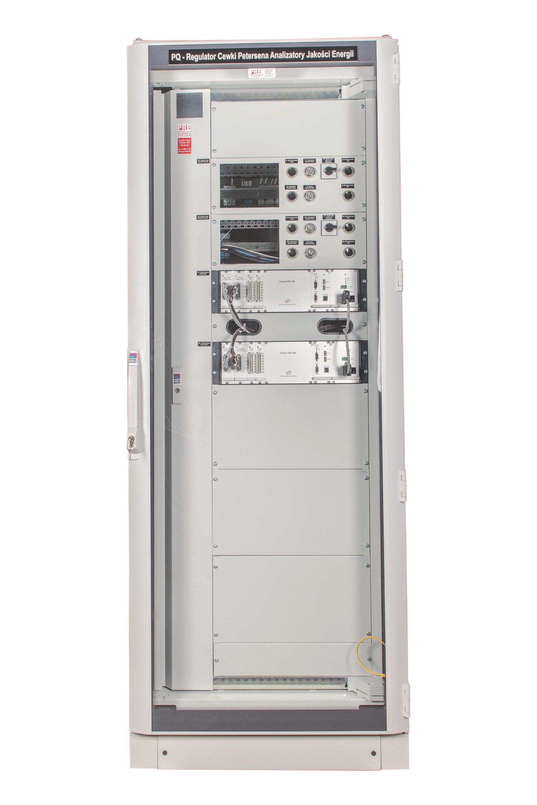
- Telecommunications – Collection and transmission of information from the station to the operator. Equipped with communication and connectivity apparatus adapted to the station configuration.
Configuration and equipment of the cabinets is each time prepared individually.
Equipment
Housing
Steel OU-1/OU-2 lub Aluminum OU-1/OU-2
- Indoor, free-standing or wall-mounted on a pedestal;
- Skeletal, made of steel frame covered with steel or aluminum sheet (connection by welding and bolted joints);
- powder-coated in any color (RAL) and surface texture with high resistance to deterioration;
- combined with plinth;
- polyurethane foam gaskets;
- made in protection class I or II;
- Degree of protection up to IP 55;
- Mechanical resistance: up to IK 8-10.
Mounting elements
- Vertical mounting profiles – steel, hole-punched, mounted to the frame;
- mounting plate – galvanized, mounted on vertical mounting profiles made of galvanized sheet metal under the current track insulators;
- koryta grzebieniowe – o przekroju dostosowanym do rodzaju i ilości okablowania;
- Cable holders with mounting bar;
- Masking plates – made of plastic plates or metal sheets, mounted to the housing structure or internal frame, with the help of mask plate brackets;
- control panel with synoptic board – made in a unique way, by applying offset printed adhesive sheets to the entire surface of the board, with the possibility of printing any graphics. Mounted in an internal frame;
- Lighting – two fluorescent lamps, assembled in the upper part, thanks to which we get an even intensity of lighting across the width. In the cabinet are mounted limit switches and a panel switch (it is possible to mount the apparatus anywhere, according to customer requirements);
- Ventilation – allowing constant airflow through the use of a fan and proper opening of the housing.
Frame – steel frame
- Made of steel profiles joined by welding;
- has a hole for attaching a mounting plate or vertical mounting profiles.
Side covers
- Mounted to the frame with allen key screw connections;
- The thickness of the sheet metal adapted to the dimensions;
- When the side covers are installed, the width dimension of the housing does not change.
Doors
- solid or transparent;
- single-sided or double-sided (back cover), for better access to the apparatus;
- Single-leaf or double-leaf;
- Locked with a cylinder lock (any shape) or a basquil lock locked with a system cylinder and an additional padlock;
- three-point locking;
- internal hinges;
- opening angle 120 deg;
- Grounding studs with wiring.
Roof
- Made of a height-adjustable cover for additional ventilation;
- The cover has an additional hole, with grommets, to allow the introduction of wiring from cable routes;
- Transport handles.
Basis
- Has an opening to allow the insertion of cables from the cable duct;
- Prepared for the fire bulkhead, using bolted connections.
Dimensions
Dimensions adapted to the type, amount of equipment and individual needs of the customer.Typical implementations:
- height: 1800/2000/2200 mm;
- width: 400/600/800/850/1000/1050/1250/1400 mm;
- depth: 250/300/400/600/800 mm.
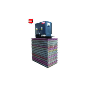
Accessories
- Plinth made in solid or ventilated version of any height.
Wiring
- Wiring of cabinets is made by wire or insulated wire with cross sections selected for the type of circuit and apparatus.
Signs
- External marking of cabinets is made, using laser engraving technique, on metal or plastic plates of any color. Marking of apparatus and wiring is carried out on the basis of the PN-EN 61082-1 standard. Electrical apparatus are described according to the internal wiring diagram and according to the design guidelines. Synoptic boards made in a unique way, by applying off-set printed sheets to the entire surface of the mounting plate, with the possibility of printing any graphics.
Rated parameters
| Rated switching voltage: | 24-48 V / 110V / 220 V /230 V/400 V |
| Rated insulation voltage: | 500 V |
| Rated frequency: | AC / DC |
| Degree of protection: | IP: 44 – 55 / IK: 08 – 10 |
| Protection class: | I/II |
Compliance with standards
PN-EN 61439-1
“Low-voltage switchgear and controlgear.-Part 1: General Provisions”;
IEC/EN 60529
” Degrees of protection provided by enclosures (IP Code)”;
PN-EN ISO 4628
“Paints and varnishes – Evaluation of deterioration of coatings – Determination of the amount and extent of damage and the intensity of uniform changes in appearance – Part 6: Evaluation of the degree of chalking by the tape method.”
PN-EN ISO 2409
“Paints and Varnishes – Testing by the Notch Grid Method.”