
Application
- in terms of electricity distribution
- protection of outlet circuits on the nN side
- protection of electrical equipment against the effects of short circuits and surges and in distribution networks
- for balancing energy consumption and control measurements
- can operate in TN-S, TN-C, TN-C-S, TT and IT three-phase networks
- designed to be mounted under a transformer on a pole
Equipment
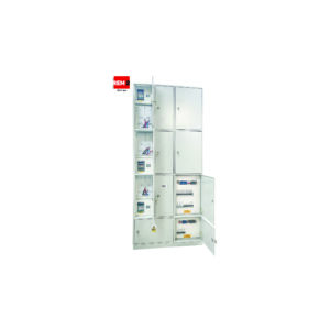
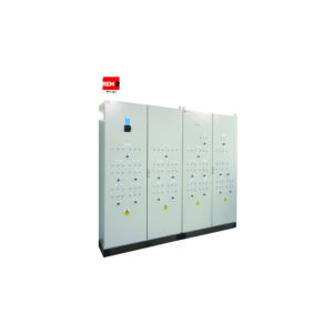
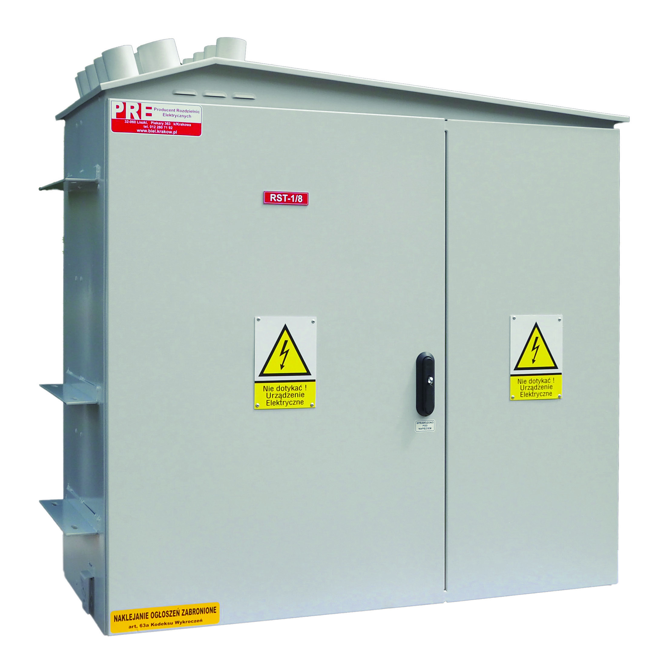
Enclosure
Aluminum OU-1/OU-2
- aluminum sheet of minimum thickness: 2 mm, bent, joined with welds, suitable for side fixing;
- High mechanical strength and degree of protection,
- which prevents dust ingress and mechanical damage;
- Powder coated in any color (e.g.: RAL 7032, 7035);
- The dimensions of the switchboard are arbitrary, adapted to the individual needs of the customer.
- The aluminum housing is made in protection class I or II.
Enclosure
Common features of the enclosures OU
- Double-sided doors, separate for each module,
- Opening at 180 degrees, three-point locking;
- Interior hinges with an anti-burglary catch;
- Basquil lock lockable with padlock or system cylinder;
- gable or envelope roof equipped with fireplaces
- with diameters adapted to the dimensions of multi-finger shrink heads;
- The bottom of the enclosure has an opening that allows cables to be inserted through the cable channel;
- marking of the switchgear with durable engraved plastic plates, allowing identification of all relevant components.
The housing has a ventilation maze to prevent water and moisture accumulation.
Accessories
- K-AL cable duct, made of aluminum sheet or composite, in any color. The dimensions of the channel are adapted to the number of circuits and the height of the housing installation;
- FM metal or FB concrete foundation that allows the switchgear enclosure to be placed as a free-standing enclosure at the station pole;
- OM mounting clamps made of galvanized steel profiles, allowing direct mounting of the switchgear on the pole.
- The design of the housing provides any spacing and shape of the clamps;
- “P” base allows additional support and support points for the switchgear enclosure with non-standard equipment, such as increasing the number of apparatus and devices, rail cross-section.
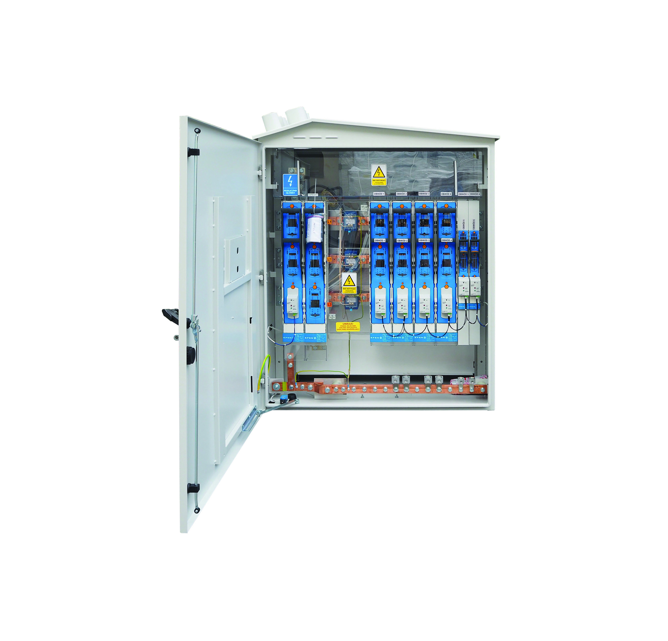
Current paths
- Current paths made of bolted copper flat bars with a cross-section matched to the current load, equipped with pressed-in rivet nuts to allow installation work on live strip apparatus;
- PEN bus with the possibility of splitting into PE and N.
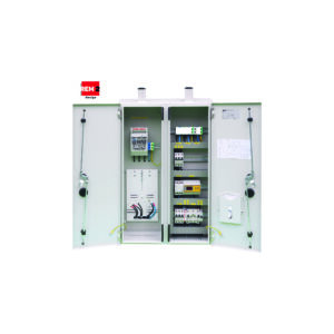
Configuration
MZ/MO – supply and drain module
- Power supply made by separate V or VLM type terminals for two cables up to 2x4x240A and 4x240A;
- Feeding strip and box fuse disconnectors or power circuit breakers: 400/630/910/1250 A with KPW fuse-layer burnout control or without fuse-layer burnout control;
- Power supply to the generator field 400 A/630 A strip disconnector;
- Outlet disconnectors or fuse bases of strip and box fuses 160/250/400/630/910 A with or without KPW fuse-link burnout control;
- Current transformers of the measuring and balancing module selected in accordance with the guidelines of the distributor and energy seller;
- Shielded reserve circuits without and with control of insert burnout.
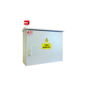
MP – measuring-balancing module in accordance with the guidelines of the distributor
and energy sellermeasuring-balancing module in accordance with the guidelines of the distributorand energy seller
SON – lighting module, a system for controlling the street lighting of the traffic route around the station.
Rated parameters
| Rated switching voltage: | 230/400 V |
| Rated insulation voltage: | 690 V |
| Rated frequency: | 50 Hz |
| Surge voltage withstanding: | 12 kV |
| Rated continuous current of the main rails: | 400/630/910/1250 A |
| Rated continuous current of drain rails; | 160/250/400/630/910 A |
| Rated short-term withstand current: | 20 kA (1 s.) |
| Rated peak withstand current: | 40 kA |
| Short-circuit current of internal arc discharge: | 16 kA |
| IP rating: | 44 |
| IK degree of mechanical resistance: | 10 |
| Protection class: | I/II |
| Network layouts: | TN-S, TN-C, TN-C-S, TT, IT |
| Height/Width/Depth: | unbound |
Compliance with standards
PN-EN 61439-1
“Low-voltage switchgear and controlgear – Part 1: General provisions”;
PN-EN 61439-2
“Low-voltage switchgear and controlgear – Part 2: Switchgear and controlgear
for power distribution””Low-voltage switchgear and controlgear – Part 2: Switchgear and controlgearfor power distribution”
PN-E-05163
“Shielded low-voltage switchgear and controlgear. Guidelines for testing under arc discharge conditions resulting from an internal short circuit”;
PN-EN 50274
“Low-voltage switchgear and controlgear – Protection against electric shock – Protection against unintentional direct contact of hazardous live parts”;
PN-EN 62208
“Empty enclosures for low-voltage switchgear and controlgear. General requirements”;
PN-EN 60529
“Degrees of protection provided by enclosures (IP Code)”;
PN-EN ISO 4628
“Paints and varnishes – Evaluation of damage to coatings – Determination of the amount and extent of damage and the intensity of uniform changes in appearance – Part 6: Evaluation of the degree of chalking by the tape method.”
PN-EN ISO 2409
“Paints and Varnishes – Testing by the Notch Grid Method.”
PN-EN 62262
“Degrees of protection against external mechanical impact provided by enclosures of electrical equipment (IK code) (IDT PN-EN 50102:2001)”.