Application
- In low-voltage apparatus (fuse disconnectors, fuse bases, isolating disconnectors) and busbars, it allows the connection of conductors of multi-strand sector, sector solid, round multi-strand and round solid (VLM) cables by means of an Allen key No. 6;
- Connection of conductors directly to the current and PEN buses;
- Creation of flexible connections between the busbars of each phase;
- For connections with high mechanical strength and current conductivity (weak heating).
Advantages
VLM and ZLM screw terminals are made of cast brass alloy. They are characterized by:
- High quality workmanship;
- Current resistance (rated, short-circuit);
- Mechanical strength, including: bending and pulling;
- Very good resistance to temperature rise;
- High tightening torque VLM-240 – 35Nm, VLM-300 – 40Nm, ZLM-2×300 – 40 Nm;
- Resistance to corrosion and wear.
Brass clamps with their parameters are far superior to the aluminum clamps previously used. An important advantage is the absence of ripples and shrinkage cavities in the casting and the strengthening of the surface layer.
Material
VLM and ZLM terminals are made of CC 754 S (Mo59) cast brass alloy, which includes up to 60% Cu. The terminals are made by gravity pouring. All elements of the terminal are tin-coated.
Construction
The VLM and ZLM terminals were constructed based on experience and feedback from the energy market.
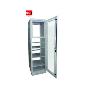
Openwork floor
Made from steel profiles to any size. Mounted a short distance from the floor on special adjustable brackets, which allows accurate leveling of the floor. Elements of the structure are joined using welds, then the structure is subjected to the process of galvanizing and powder coating in any color.
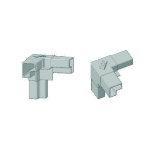
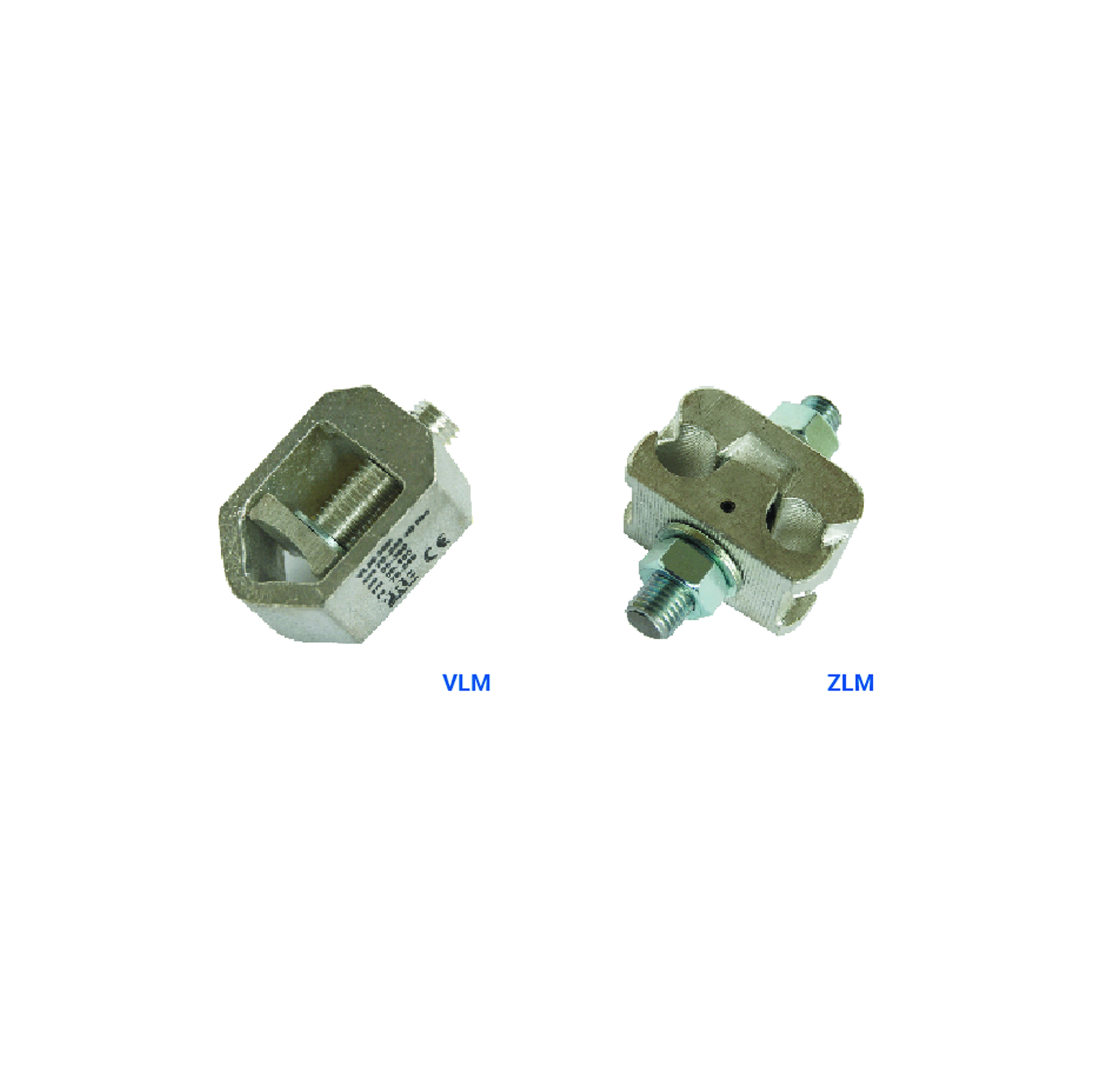
VLM screw terminal
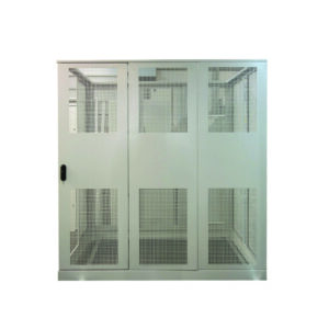
Any shape of partition structure made of a frame of profiles of any cross-section. The structure is filled with galvanized or powder coated mesh. The type and density of the mesh depends on the purpose of the partition and is selected individually. Partitions are made as stationary or hinged in the form of a lockable door.
The clamp includes a body, the construction of which was designed to carry higher loads than similar clamps made of aluminum. The effect was achieved by making thickenings in the lower part of the body and thickening the side walls by min. 2 mm each. To a large extent, this allowed the tightening strength to be increased.
The other components of the clamps are a screw equipped with a socket for a No. 6 allen key and a specially shaped clamp that allows the cable conductor to be inserted within the range:
- VLM-240 – 35-240mm;
- VLM-300 – 70-300 mm.
ZLM screw terminal
The clamp consists of two brass parts, an M16 threaded rod locked with a pin, two washers and nuts. The lower part with the threaded rod has a perforated contact surface with the current bus and PEN, which provides maximum contact area.
The upper part of the terminal movable by appropriate profiling of two holes allows the connection of two conductors of one phase, within the range:
- ZLM-2×300 – 2 x 35-300mm.
The design of the terminal allows it to be mounted on the copper current rail at different angles vertically, horizontally or diagonally. In the case of a larger number of cables, it is possible to mount two terminals simultaneously, paying special attention to the value of the long-term current. The design of the terminal allows it to be mounted on a rail of any cross-section. For jointed rails of more than 10mm, it is necessary to order a terminal with a longer threaded rod.
Accessories
Along with the clamps are available:
- Type I terminal switch (W1 and W2) for VLM-240, VLM-300;
- C-type terminal connector for VLM-240, VLM-300;
- Terminal insulation cover made of polyamide in various colors according to RAL.
General characteristics and ratings of screw terminals
| Type of terminals | VLM-240 | VLM-300 | VLM-2×300 |
| Rated short-lasting withstand current Icw (kA) | 22,2 kA, 1 s. | 28,8 kA, 1 s. | 28,8 kA, 1 s. |
| Rated peak withstand current Ipk (kA) | 46,6 kA | 60,5 kA | 60,5 kA |
| Average terminal temperature during short circuit (°C) (W1/W2) | 66/125 °C | 76 °C | – |
| Rated Connectivity : | |||
| – sm | 50 ÷ 185 mm2 | 70 ÷ 240 mm2 | 50 ÷ 240 mm2 |
| – se | 50 ÷ 240 mm2 | 95 ÷ 300 mm2 | 50 ÷ 240 mm2 |
| – rm* | 35 ÷ 96 mm2 | 50 ÷ 185 mm2 | 35 ÷ 300 mm2 |
| – re | 35 ÷ 120 mm2 | 70 ÷ 240 mm2 | 50 ÷ 150 mm2 |
| Tightening torque of the clamp screw (Nm) | 35 Nm | 40 Nm | 40 Nm |
| Clamp weight (g) | 170 g | 195 g | 742 g |
Compliance with standards
PN-EN 60947-7-1:2012
“Low-voltage switchgear and controlgear – Part 7-1: auxiliary equipment – terminal blocks for copper conductors;
PN-EN 60947-7-2:2012
“Low-voltage switchgear and controlgear – Part 7-2: Ancillary equipment – Protective conductor terminal blocks for copper conductors;”
PN-EN 60999-1:2002
“Connecting Fittings – Copper Electrical Conductors – Safety Requirements for Threaded and Threadless Clamping Elements – Part 1: General Requirements and Specific Requirements for Clamping Elements for Conductors from 0.2 mm2 to 35 mm2 (inclusive);”
PN-EN 60999-2:2006
“Connection fittings – Copper electric conductors – Safety requirements for threaded and threadless clamping elements – Part 2: Particular requirements for clamping elements for conductors with cross-sections greater than 35 mm2”.