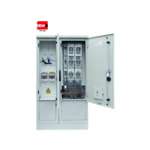
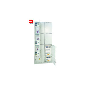
Application
- For indoor and container SN/nN transformer stations;
- For industrial and construction facilities;
- Power supply, distribution and metering of electricity and protection of electrical equipment from the effects of short circuits and overloads on the low-voltage side.
Equipment
Enclosure
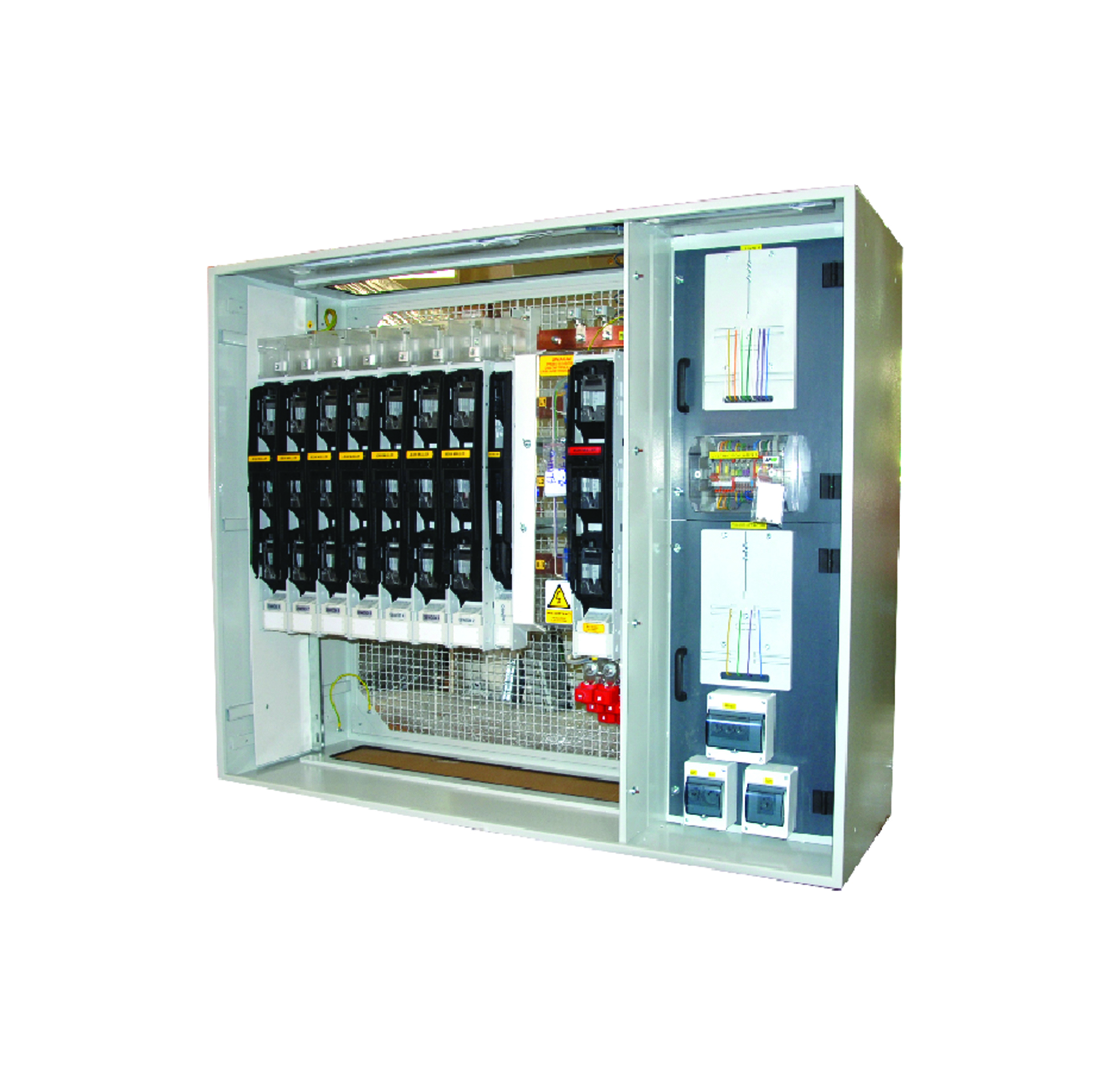
- Small-sized, lightweight, modular, providing adequate structural rigidity; made of galvanized steel or aluminum profiles connected by cast connectors;
- High mechanical strength and a degree of protection that prevents the ingress of dirt and mechanical damage;
- Fully shielded, covers made of steel sheet coated with anti-corrosion, powder coated in any color, made in a fixed or tilting version that allows inspection and testing with a thermal imaging camera;
- Internal space with separated parts: functional modules, current paths;
- Allows you to change the power supply side independently, either by repositioning the switchgear power module or swapping it with the metering module;
- Connection of individual modules made by screw connections (without riveting or welding) allows quick disassembly of modules, bringing the switchboard in modules to the place of foundation in the room (lack of space) and their reassembly;
- Set on an additional frame, matching the dimensions of the cable channel;
- The dimensions of the switchboard are arbitrary, adapted to the individual needs of the customer;
- The possibility of combining several modules;
- Handles that allow transportation by crane or overhead crane;
- marking of the switchboard with permanent engraved plastic plates, allowing identification of all relevant components.
Current paths
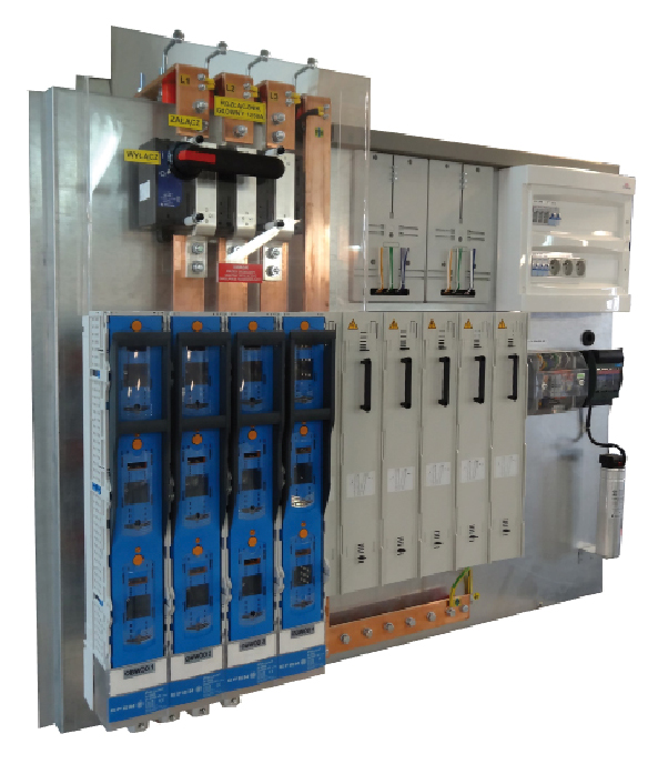
- Current paths of the supply and discharge module made of screwed copper flat bars with a cross-section adapted to the current load, equipped with pressed-in rivet nuts to enable installation work on current-carrying band apparatus.
- Portable grounding terminal connection rail;
Configuration
power supply module
- Module power supply made as rail or cable power supply
- With the help of terminals on the rails of the current track;
- Power rail bridge fully covered;
- Isolating or fuse disconnector or power circuit breaker up to 2500 A;
- Grounding brackets for connecting grounding devices;
- Optionally, the module can be equipped with PK/EQ
Current drain module
- disconnectors or fuse bases (letter or box);
- Optionally, the module can be equipped with additional elements,
- e.g., genset disconnect switch;
- shielded reserve circuits;
- cable clamps
- As required with KPW insert burnout control,
- without liner burnout control
Metering-balancing module in accordance with the guidelines of the distributor
and energy seller;
SON – lighting module, circuit for controlling street lighting of the traffic route in the vicinity of the station;
OPW – own-needs circuits, station lighting;
PK/EQ – control measurement, power quality analysis, measuring transformers, network parameter meter (analog or digital), power quality parameter analyzer, communications;
BK – transformer idle compensation capacitor / capacitor bank.Metering-balancing module in accordance with the guidelines of the distributorand energy seller;
SON – lighting module, circuit for controlling street lighting of the traffic route in the vicinity of the station;OPW – own-needs circuits, station lighting;
PK/EQ – control measurement, power quality analysis, measuring transformers, network parameter meter (analog or digital), power quality parameter analyzer, communications;
BK – transformer idle compensation capacitor / capacitor bank.
Additional
The RWT switchgear is additionally equipped with OPW auxiliary circuits, which include:
- station lighting (16 [A]/ D01)
- socket 230 [V] (16 [A]/D01)
- additional circuit protection required by the customer
Rated parameters
| Rated switching voltage: | 230/400 V |
| Rated insulation voltage: | 500/690 V |
| Rated frequency: | 50 Hz |
| Surge voltage withstanding: | 6/8/8 kV |
| Rated continuous current of the main rails: | 1250/1600/2500 A |
| Rated continuous current of drain rails; | 25/25/40 kA |
| Rated short-term withstand current: | 25/25/40 kA |
| Rated peak withstand current: | 52,5/52.5/84 kA |
| Short-circuit current of internal arc discharge: | 20 kA |
| IP rating: | 4X/2X |
| IK degree of mechanical resistance: | 10 |
| Protection class: | I |
| Network layouts: | TN-S, TN-C, TN-C-S, TT, IT |
| Height/Width/Depth: | unbound |
Compliance with standards
PN-EN 61439-1
“Low-voltage switchgear and controlgear – Part 1: General provisions”;
PN-EN 61439-2
“Low-voltage switchgear and controlgear – Part 2: Switchgear and controlgear
for power distribution”;”Low-voltage switchgear and controlgear – Part 2: Switchgear and controlgearfor power distribution”;
PN-E-05163
“Shielded Low Voltage Switchgear. Guidelines for testing under arc discharge conditions due to an internal short circuit”;
PN-EN 50274
“Low-voltage switchgear and controlgear – Protection against electric shock – Protection against accidental direct contact with hazardous live parts”;
PN-EN 62208
“Empty enclosures for low-voltage switchgear and controlgear. General requirements”;
PN-EN 60529
“Degrees of protection provided by enclosures (IP Code)”;
PN-EN ISO 4628
“Paints and varnishes – Evaluation of deterioration of coatings – Determination of the amount and extent of damage and the intensity of uniform changes in appearance – Part 6: Evaluation of the degree of chalking by the tape method.”
PN-EN ISO 2409
“Paints and Varnishes – Testing by the Notch Grid Method.”
PN-EN 62262
“Degrees of protection against external mechanical impact provided by enclosures of electrical equipment (IK code) (IDT PN-EN 50102:2001)”.

